Look at the rotor
On a typical hub motor, the magnets line the inside of the rotating outer shell. Their alternating north and south magnetic regions are the poles.
Find the magnetic pole count in your motor. Each north and south pole makes one pair.
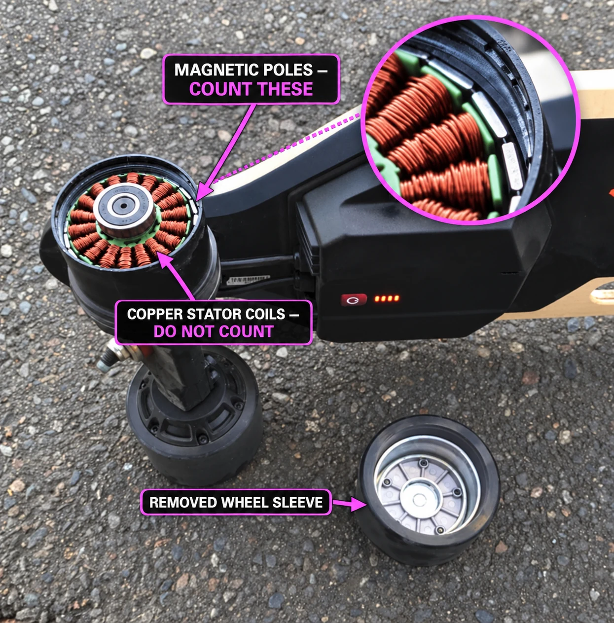
The pink callout points to the magnet ring on this mounted hub motor. The orange copper windings and the removed wheel sleeve are separate parts. Open full-size image ↗
The diagram separates the magnetic rotor from the copper stator so you can see the pattern. Count the alternating N and S magnetic regions, then divide by two.
This is a teaching diagram, not an exploded view of one board. The little rim dots represent fasteners, which do not determine pole pairs. On the photographed board, the visible magnet ring stays with the motor when the wheel sleeve is removed.
Count the alternating magnetic regions around the rotor. Enter an even number from 2 to 60.
Electrical RPM depends on how many pole pairs pass the stator in one physical revolution.
Motor RPM × pole pairs = ERPM
On a typical hub motor, the magnets line the inside of the rotating outer shell. Their alternating north and south magnetic regions are the poles.
One north pole plus one south pole makes a pair. For example, 14 magnetic poles mean 7 pole pairs.
Sleeve screws and copper stator teeth are different parts. Their counts do not tell you the motor's pole pairs.
A physical magnet piece can contain more than one magnetic region. Use the manufacturer's motor specification or measure the magnetic poles if counting pieces is unclear.
The photo is an annotated visual reference, not a specification for your particular motor. Confirm pole count with its manufacturer when possible.